
|
Hovercrafts
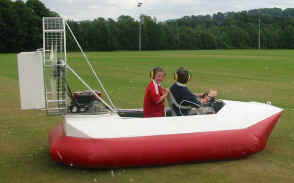
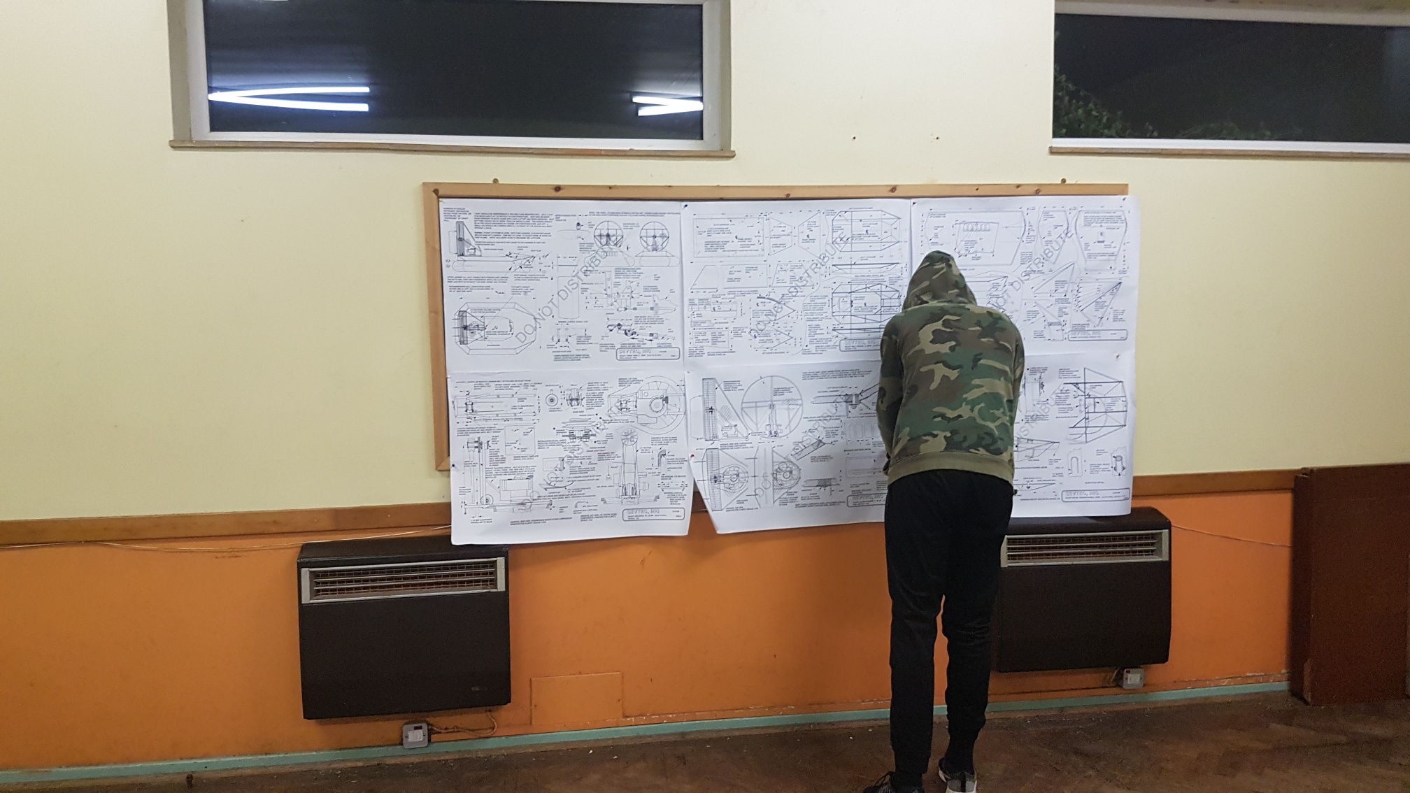
We set out to build a hovercraft with our scouts! No, really, a hovercraft, from scratch, made in fibreglass covered foam with a lawnmower engine driving two fans, built on Wednesday evenings following the plans for a Sevtec Scout in five stages:
When completed this hovercraft should be able to take one or two scouts out for a grin-widening ride over water and flat land.
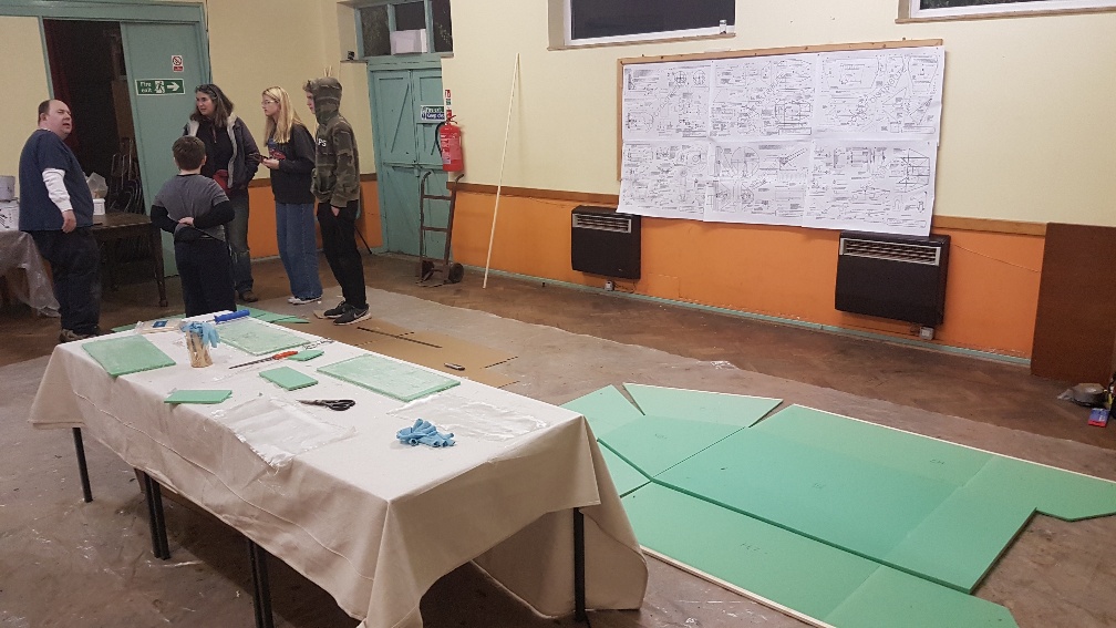
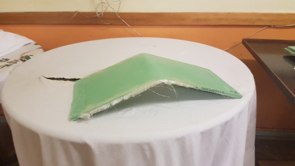
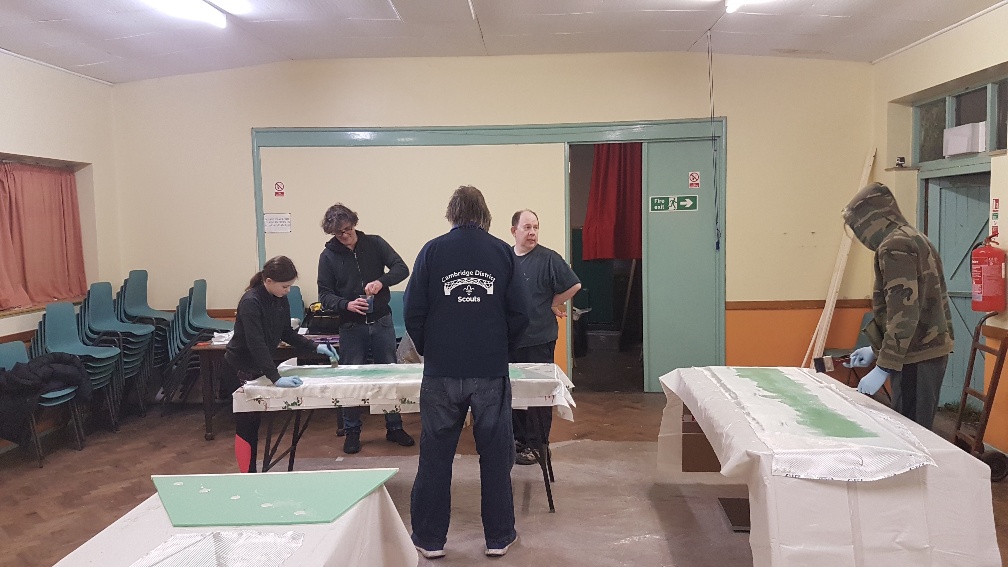
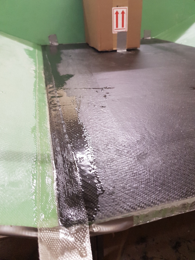
Day 1Our first day we covered some of the basics of how the hovercraft is constructed, from structural foam bonded both sides with fibreglass. The foam keeps the two stiff sides of fibreglass apart like the middle bit on an I-beam which makes for a very lightweight stiff and strong panel. Each of our scouts started on a test panel, cutting out a rectangle of 10mm foam 60cm x 25cm and fibreglassed one side. When the second side has been fibreglassed (and that has cured) it should support the scout when supported at either end between two chairs We also cut out the first two panels, H6 and H8A, which will form the base of our hovercraft and we chose to make from slightly thicker 25mm foam for extra durability
Day 2The scouts fibreglassed the other side of their test panels and we turned out attention to cutting out the rest of the tub panels, a pair of H7s and H9s and H8B. Some of these need wood bonded to the edge of them first as we will screw the skirt material into this wood. Others will need hardpoints of resin and glass beads in them for the same reason.
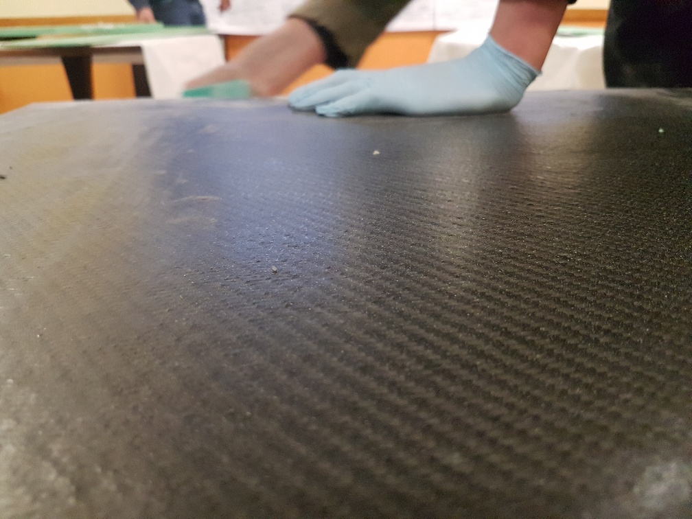
Day 3We tested our test panels that we had made .. and they failed! Our fibreglass sheeting choice was the lighter of the two available and is not strong enough. We will need to get some 200g/m2 fibre cloth and try again.
Meanwhile, we cut out the trickier end panels H1, H2x2 and H4, and cored and filled the hard-points. These are holes cut in the foam that are filled with resin impregnated with glass beads, into which we can screw down the skirt, as plain foam would just tear on its own.
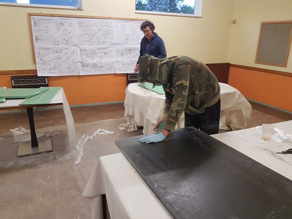
Day 4With the thicker 200g/m2 fibreglass cloth we fibreglassed one side of the larger panels (there wasn't space to do more). We also re-made one side of one of the test panels so we can see if that now passes the test
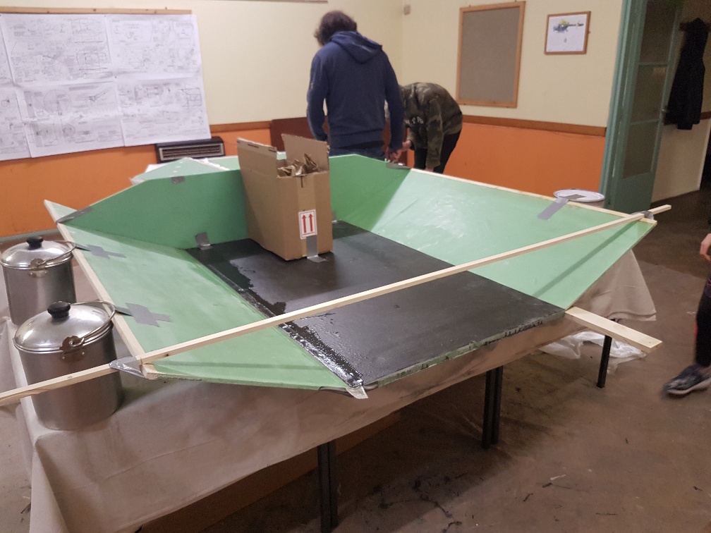
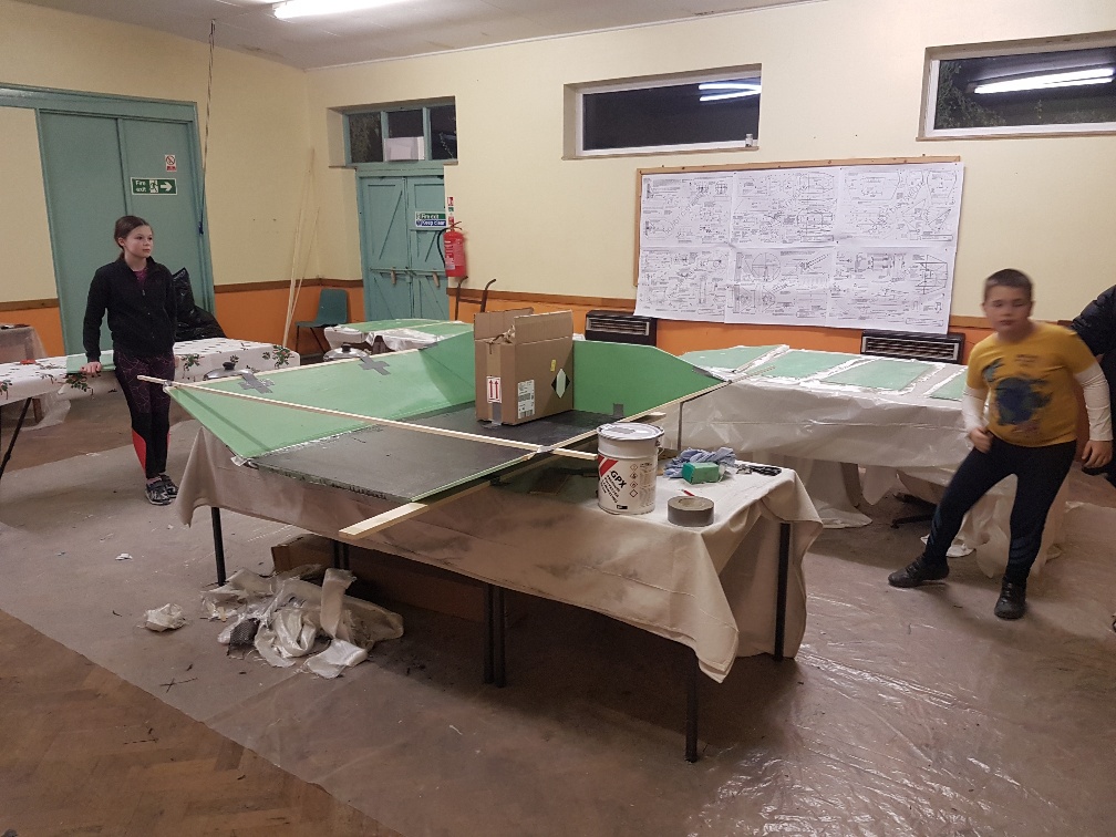
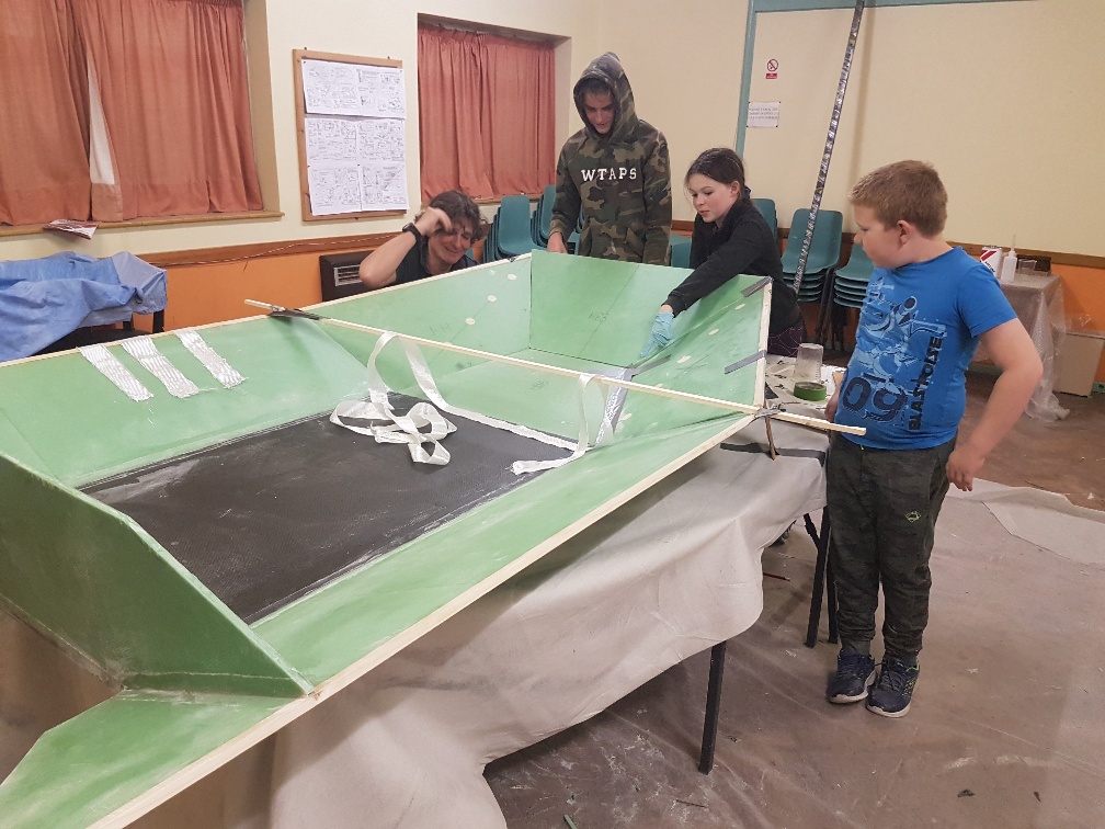
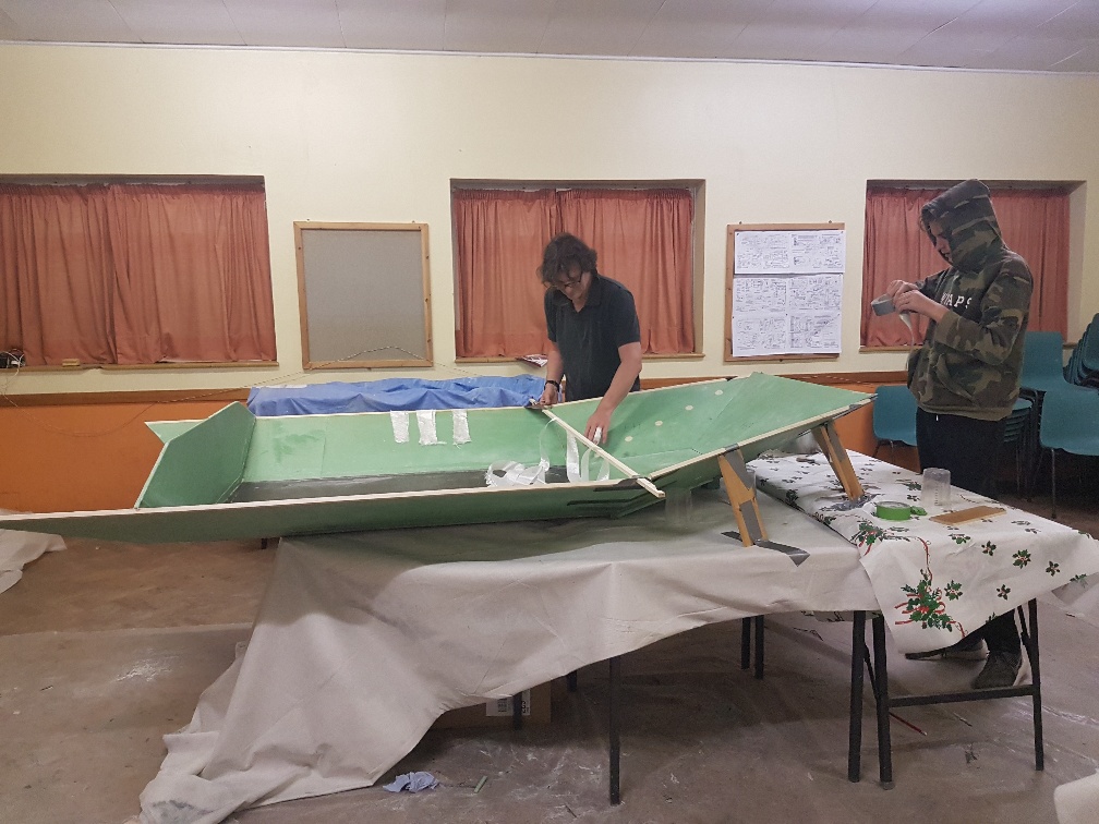
Day 5We fibreglassed a few more boards but ran out of resin so had to stop. We cut out a the fibreglass sheet for the next few pieces and then called it a night Day 6There being no scouts during Easter a couple of the leaders made use of the new resin delivery and fibreglassed the pre-prepared boards on one side Day 7We cut off the edges of the seven pieces fibreglassed the previous week and then fibreglassed the remaining side of the last seven pieces and test assembled the sides (H7) onto the base (H6) with the cockpit back plate (H1) to get the shape right. Then we sanded down the edge of the first H7 side piece at 12° which is a 2mm offset on one edge over 10mm. Using the H1 piece as a former we arranged the H7 side piece on supporting pieces of wood with some billy cans to hold it at the right angle and then fibrglass-taped the inside of the joint.
Day 8We cleaned up the remaining edges of those seven pieces fibreglassed the previous week. We sanded down the edge of the second H7 side piece at 12°. Using the H1 piece as a former we again arranged the H7 side piece on supporting pieces of wood with some billy cans to hold it at the right angle and then fibrglass-taped the inside of the joint. We then attached H1 along its entire length to join to both H7s and H6. Meanwhile we looked at how the engine would attach and what pieces were needed to be fabricated.
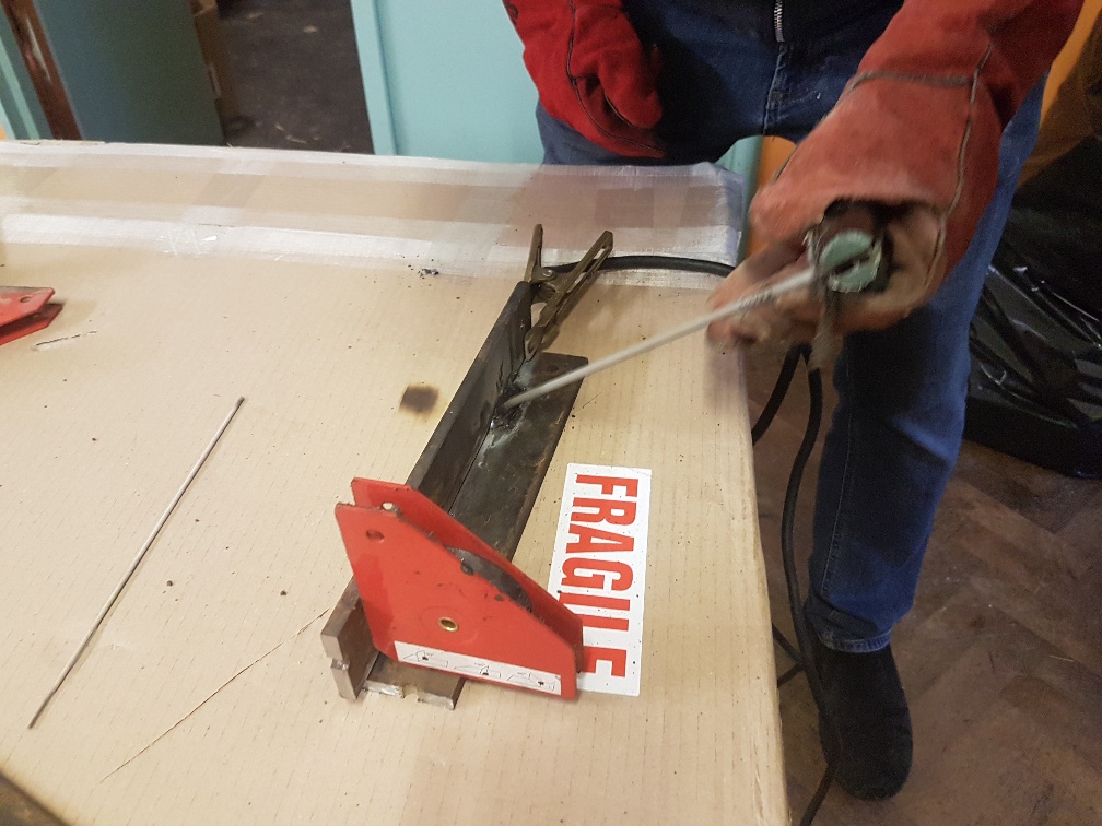
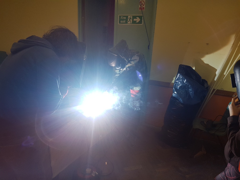
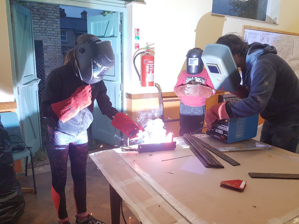
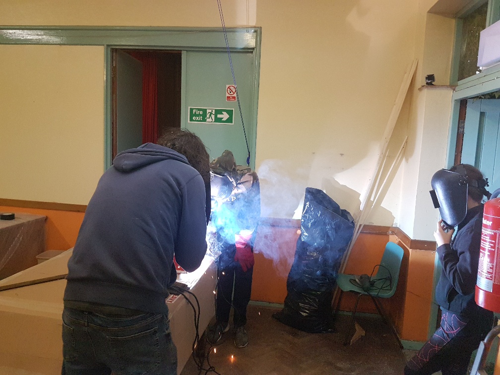
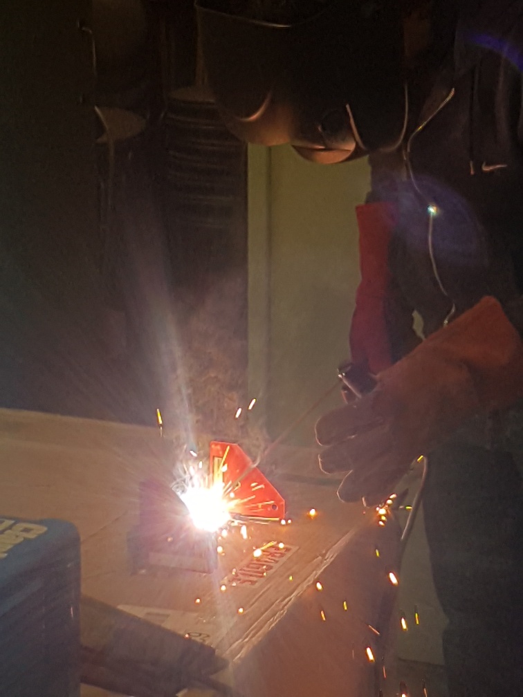
Day 9We turned our attention to the imminent welding of the drive support assembly and all had a go at welding with the arc welder. This in turn meant that some of us had to be out of the room so as to avoid 'arc-eye' where the bright UV light from the welder burns the retina. This cut down on the amount we got done that wasn't welding, but we all had a lot of fun welding so this was completely acceptable. Some fibreglassing of the seams carried on in the background
Day 10We returned to the tub and flipped it over to chamfer and the tape the joints underneath. Day 11We worked on the nose area of the tub and adjusted the parts (some had been made slightly too large), chamfered their edges and dry-fitted them ready for taping the seams next week The H9 parts were made too large because the sizes are supposed to include the wood strips that will later have the skirt screwed into, where we had left thse off and added them in later, making them around 20mm too big. They had to be cut down
We talked to our District Commissioner about our scouts being able to carry out the BSA Welding Merit Badge and, if they complete all of the prescribed requirements, having permission to wear the welding merit badge with pride alongside their other activity badges
Day 12We added the tail parts around where the lift fan will drive the air down, and started on the rear corners Day 14We started up the engine with the lift fan and drive pulley on it, on a makeshift shroud in the carpark
Day ??We started up the now caged drive unit in the carpark
| |||||||||||||||||||||||


 |
last updated: Fri Aug 4 2023 | site info |